Retrofit Install: Adding Surf Wizard to an Existing System
Use this guide if your boat already has working ballast pumps plumbed to bags, surf plates driven by 12 V linear actuators, and a 12 V house bus you trust. You are not replumbing the boat — you are inserting an ESP32-S3 bridge between the app and the wiring you already have, so your phone controls what the rocker switches do today. Plan on 3–5 hours on the bench and 2–3 hours on the boat. No hoses cut, no thru-hulls drilled.
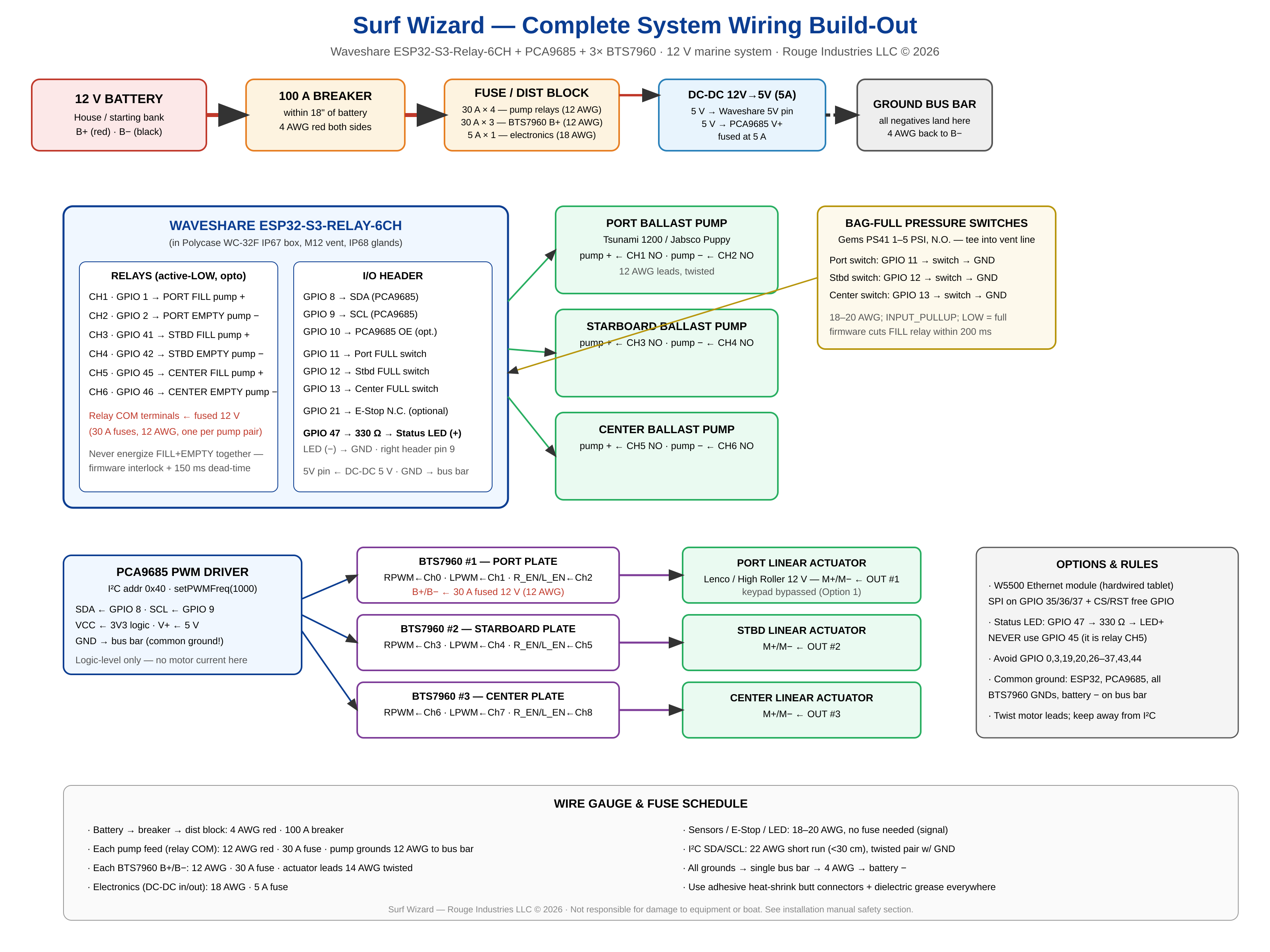
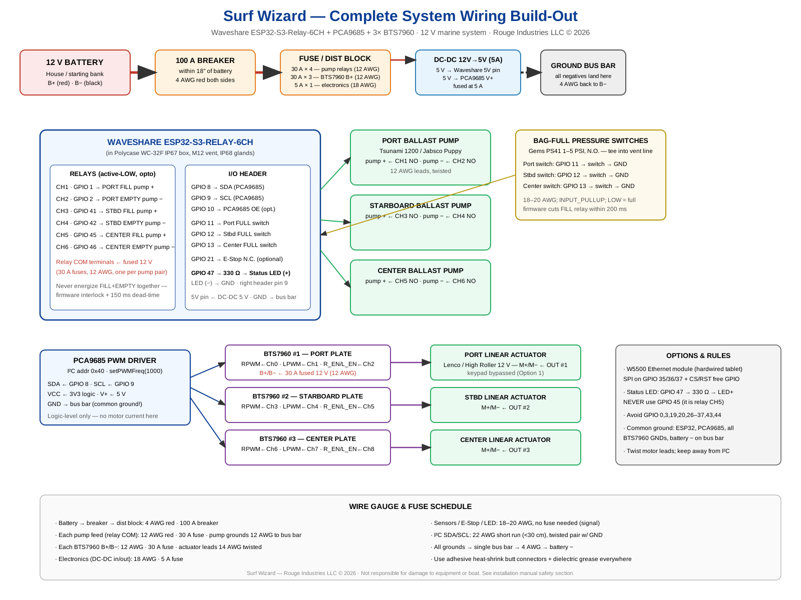
1. Pick the interception point (the one decision that matters)
Choose one option per subsystem before you order anything. Write your choices down — everything downstream depends on them.
Ballast pumps (per pump)
Pull the rocker that reverses each pump and wire the pump's motor leads to a FILL and EMPTY relay pair on the bridge. Cleanest, and what the pinout document assumes.
Leave the OEM controller in place and drive its low-current input lines from bridge relays as dry contacts. Choose this if the OEM controller has flow sensors, auto-off, or bag-full logic you want to keep.
Surf plates (12 V linear actuators — no servos in this system)
Land the actuator's two motor leads on a BTS7960 (M+ / M−). Its control pins come from the PCA9685 (channels 0–8 at 1000 Hz), which gives smooth proportional positioning through timed strokes.
EXTEND and RETRACT on spare bridge relays, leaning on the actuator's built-in limit switches. Simplest, but position feedback becomes on/off instead of proportional.
2. Parts you actually need
You are not buying pumps, bags, hoses, thru-hulls, plates, or actuators. This is only the control-layer add.
| Qty | Item | Notes |
|---|---|---|
| 1 | Waveshare ESP32-S3-Relay-6CH | The bridge — ESP32-S3 with six on-board relays |
| 1 | PCA9685 16-channel PWM driver | Logic-level control for the actuator H-bridges |
| 3 | BTS7960 43 A H-bridge module | One per surf-plate actuator |
| 1 | DC-DC buck converter, 12 V to 5 V, 3 A | ESP32 and logic rail |
| 3 | 30 A fuse + holder | One per actuator feed, straight off the 12 V bus |
| 1 | Latching E-Stop, 22 mm normally-closed, IP65 | Mushroom head, dash or console mount |
| 1 | Sealed enclosure, IP66, ~200×150×100 mm | Skip if the bridge already lives in a case |
| 4 | IP68 cable gland, PG-13.5 | Power and signal pass-through |
| 2 | 5 A ATC fuse + inline holder | Bridge power feed |
| 1 pack | Heat-shrink butt connectors, mixed AWG | Adhesive-lined |
| 1 roll | 18 AWG marine tinned wire, red and black | Relay-to-load runs |
| 1 | USB-C data cable | Firmware flashing |
If you already own a sealed junction box and a multimeter, your total add is roughly one relay bridge, one E-Stop, and a handful of connectors.
3. Bench bring-up — before the boat
- 1Flash the ESP32-S3 firmware and confirm it boots and joins your network.
- 2Wire the relay board and PWM driver per the bridge pinout.
- 3With no load connected, command port ballast to FILL and confirm the fill relay clicks while the empty relay stays off. Send stop, then empty, and confirm it flips. Repeat for starboard and center.
- 4Prove the interlock: toggling fill straight into empty must insert a stop of at least 100 ms in between. Watch the relay LEDs.
- 5Press the E-Stop. Every relay LED must go dark and stay dark until you release the button and clear the E-Stop from the app.
- 6Wire the PWM driver to the H-bridge control pins, power one actuator on the bench, and command 0, 50, and 100. It must extend, retract, and never drive both directions at once.
Do not proceed to the boat until every one of these passes.
4. Printable wiring diagrams
Print these and tape them inside the enclosure lid — future-you will thank present-you.
- Ballast reversing relays (SVG) · PDF — one set per pump: port, starboard, center
- Surf-plate linear actuators (SVG) · PDF — BTS7960 H-bridge wiring per actuator
- Status LED (SVG) · print-ready PNG
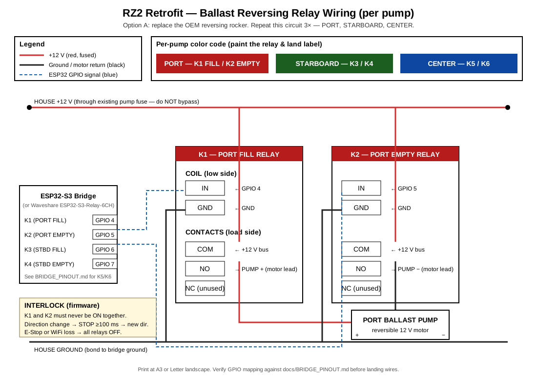
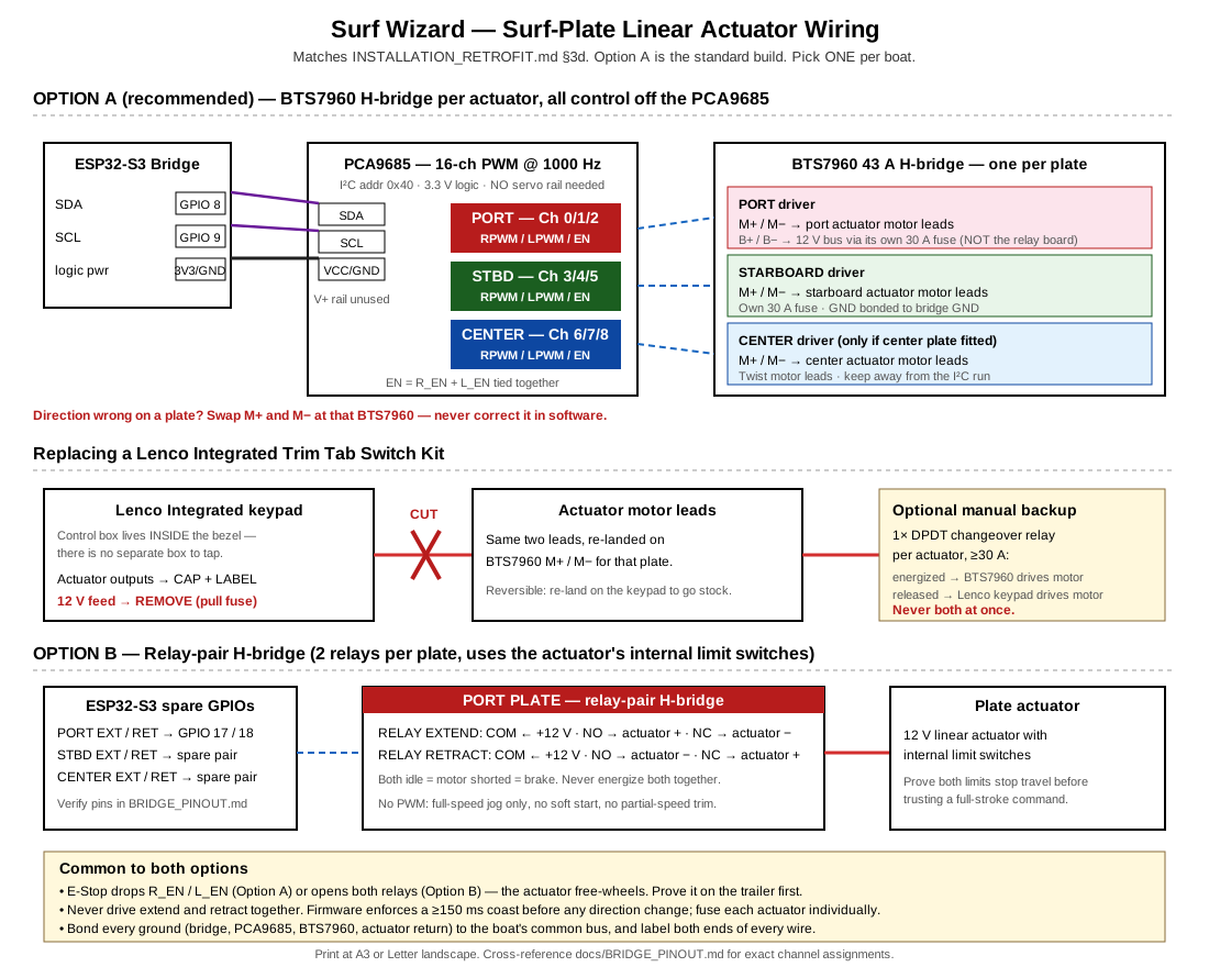
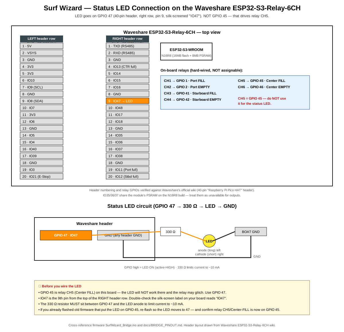
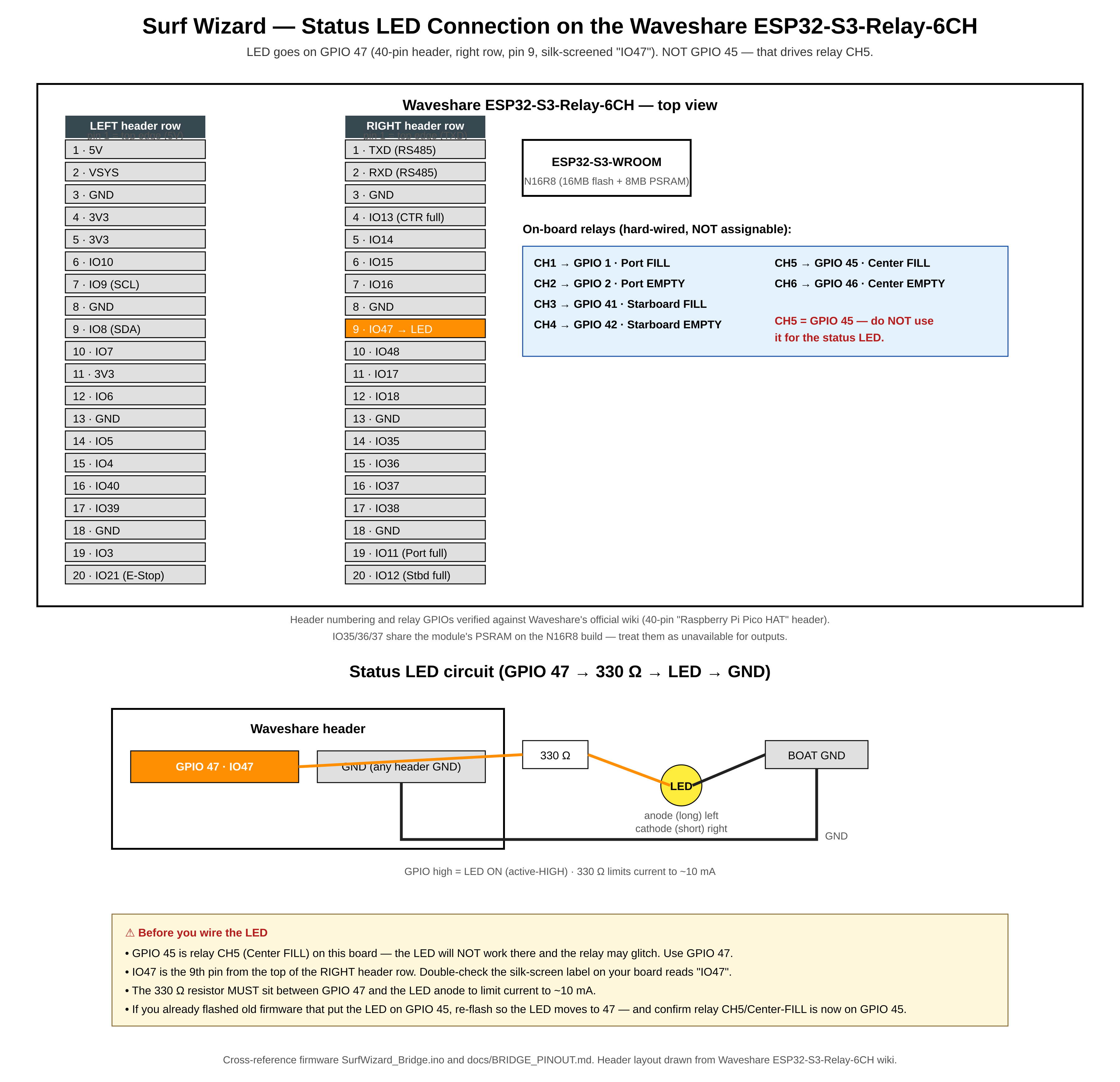
Color coding used in every diagram: red is fused +12 V, black is ground or motor return, dashed blue is an ESP32 signal, purple is I²C. Paint or heat-shrink the physical relays to match, and use red for port, green for starboard, blue for center.
5. On-boat install
Kill power
Master battery switch off, then confirm 0 V at the ballast fuse block with a multimeter.
Mount the enclosure
Dry location, out of direct spray, within cable reach of the pump relays and the plate driver. Vent facing down, 100 mm service loop on every cable.
Ballast wiring, per pump
Option A: disconnect the pump motor leads at the existing rocker, route them to the bridge, land motor + on the FILL relay's normally-open contact and motor − on the EMPTY relay's normally-open contact, and take both relay commons to the pump's 12 V feed through the existing pump fuse — never bypass that fuse.
Option B: find the low-current FILL and EMPTY input lines on the OEM controller, wire each bridge relay as a dry contact across that input and its reference ground, and leave the OEM rocker in circuit as a manual override that still works when the bridge is unpowered.
Surf-plate wiring
Land each actuator's two motor leads on its BTS7960 M+ / M−. Battery leads go straight to the 12 V bus through their own 30 A fuse — never through the relay board. Control lines come from the PWM driver: port on channels 0/1/2, starboard on 3/4/5, center on 6/7/8. Tie H-bridge ground to bridge ground, keep the motor leads twisted, and run them away from the I²C pair.
Replacing a Lenco Integrated Trim Tab Switch Kit
- 1Kill 12 V at the breaker and confirm the keypad harness is dead.
- 2Un-land both motor leads for each actuator from the keypad's output harness, then cap and label those outputs.
- 3Land those same two leads on that plate's H-bridge M+ / M−.
- 4Move the keypad's 12 V feed and ground to a spare fused circuit, or pull its fuse, so the keypad is unpowered. Never leave the keypad powered and still landed on an actuator the H-bridge also drives — two drivers fighting over one motor destroys both.
- 5Extend and retract each plate once from the app and confirm the direction matches the label. If a plate moves backwards, swap its M+ and M− — do not fix it in software.
- 6Blank the keypad hole with a bezel, or leave the keypad in place cosmetically with its harness capped.
Optional manual backup: add one DPDT changeover relay per actuator, rated 30 A or better, wired so the actuator leads sit on the H-bridge when the relay is energized and fall back to the keypad when it isn't. Drive all changeover relays from a single APP / MANUAL switch at the helm so only one driver is ever on the motor. Never bridge the two sources without the changeover.
E-Stop and bridge power
Mount the E-Stop within arm's reach of the driver's seat and run its normally-closed loop back to the bridge's E-Stop input. Test that pressing it kills every relay and parks every plate while the boat is on the trailer, not on the water. Power the bridge off the house bus through a new 5 A fuse — do not share a fuse with the pumps — and verify polarity at the buck converter input before plugging the controller in.
6. Commissioning
- 1Power the bridge, confirm it re-joins the network, and open the app. The status readout should show all three ballast systems stopped, plates centered, and no E-Stop active.
- 2Trailer test, bags empty and boat out of the water: fill each tank for two seconds, stop, empty, stop. Listen for pump run direction. Sweep each plate from one end to the other and back to center, watching mechanical clearance.
- 3Dock test, in the water with the engine off: fill each tank 10 % at a time, watching for leaks at every joint you did not touch — retrofits shake old clamps loose.
- 4On-water test at idle: fill one tank fully, then empty it, and confirm the app's reported state matches what the pumps actually do. Only then run all three tanks together.
7. Rollback plan
Because nothing was cut, you can go back to stock in under an hour. Option A ballast leads go back on the rocker switch. Option B is an unplug from the OEM controller inputs. Plates come off the H-bridges and go back on the OEM driver; if you removed a Lenco Integrated keypad, re-land its actuator outputs and restore its 12 V feed and it is fully stock again. Keep the E-Stop wired in even after a rollback — it is cheap insurance.
What this retrofit does not do
- No new flow sensing. If your OEM controller had bag-full auto-off and you chose Option A, that feature goes away — use Option B to keep it.
- No bilge or high-water monitoring; add those separately.
- No override of a stuck relay. Always leave the master battery switch reachable from the helm.